Auxiliary Blocks#
- Event-Analog Signal Multiplier
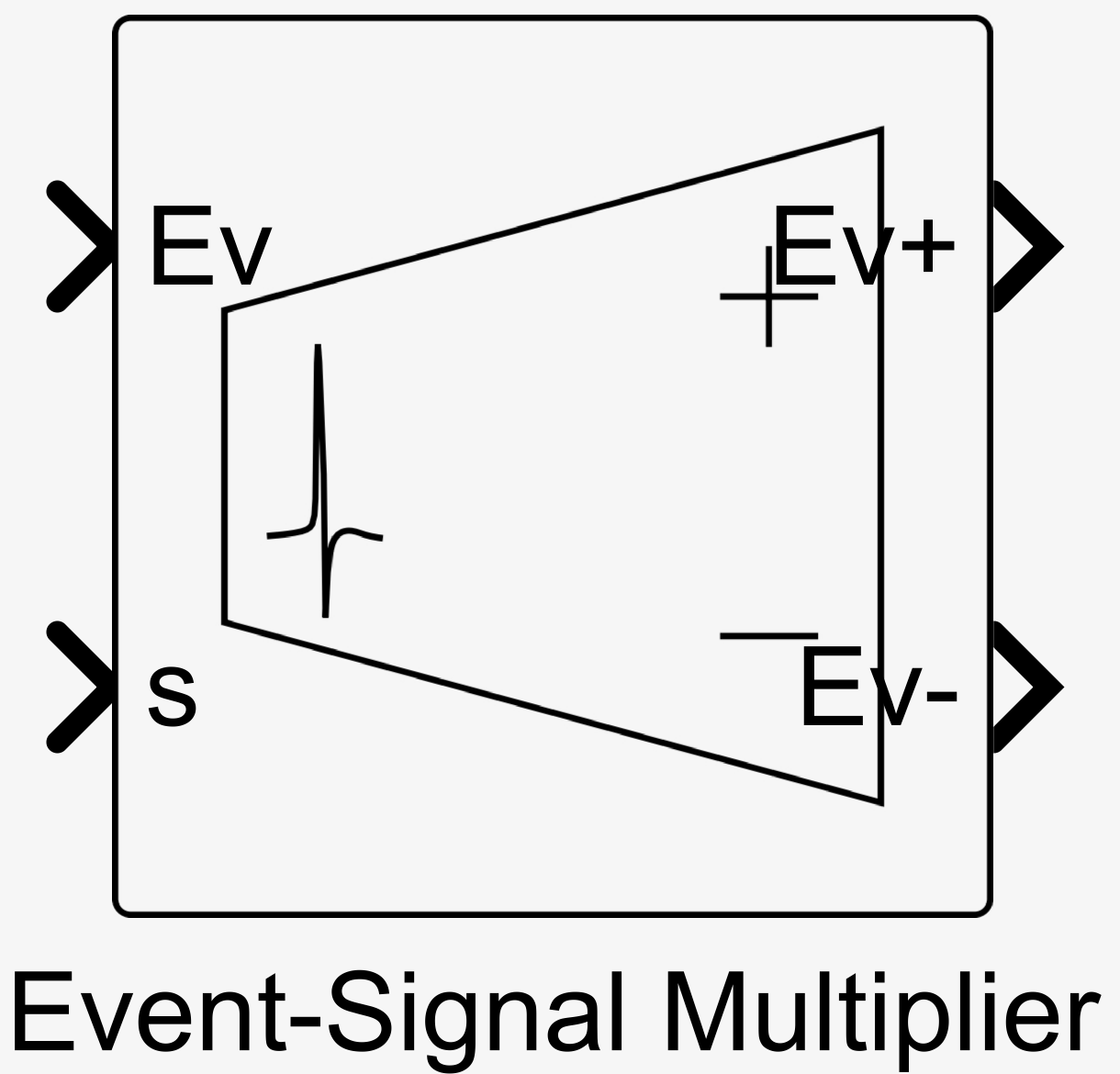
Block performing a “multiplication” between an events signal and a selection signal. The blocks can be mathematically described as:
\[\begin{split}\begin{aligned} \text{Out}_+ &= f(a_+s - d_+)\text{In}\\ \text{Out}_- &= f(a_-s - d_-)\text{In} \end{aligned}\end{split}\]where \(f\) is either a Heaviside step function \(H\) or a sigmoid function \(\sigma\) depending on the input-output type, and \(a_{\pm}\) are the slopes and \(d_{\pm}\) the biases of the selection function.
- Inputs:
Ev (boolean) – Input events signal \(\text{Ev}\) such that \(\text{In} = \text{Ev}\).
s (analog) – Input selection signal \(s\).
- Alternative Inputs:
V (analog) – Input voltage signal \(\text{V}\) such that \(\text{In} = g_{\text{in}\pm}\sigma(a_{\text{in}\pm}\text{V} - d_{\text{in}\pm})\).
s (analog) – Input selection signal \(s\).
- Outputs:
Ev+ (boolean) – Output positive events signal \(\text{Out}_+\) such that \(f \equiv H\).
Ev- (boolean) – Output negative events signal \(\text{Out}_-\) such that \(f \equiv H\).
- Alternative Outputs:
V+ (analog) – Output positive voltage signal \(\text{Out}_+\) such that \(f \equiv \sigma\).
V- (analog) – Output negative voltage signal \(\text{Out}_-\) such that \(f \equiv \sigma\).
- Parameters:
Differentiate Positive and Negative – Whether to differentiate positive and negative parameters or set the. Can be set to ‘True’ or ‘False’. Default value is ‘False’.
Signal Biases – The biases \(d_{\pm}\) of the selection function. Default value is 0.
Signal Slopes – The slopes \(a_{\pm}\) of the selection function. Default value is 1.
Input-Output Type – The exposed input-output channels. Can be set to ‘Events’ or ‘Voltage’. Default value is ‘Events’.
Input Conductances – The input conductances \(g_{\text{in}\pm}\) used if voltage input is selected. Default value is 1.
Input Biases – The input biases \(d_{\text{in}\pm}\) used if voltage input is selected. Default value is 0.
Input Slopes – The input slopes \(a_{\text{in}\pm}\) used if voltage input is selected. Default value is 1.
- Event-Analog Signal Selector
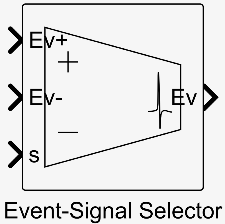
Block performing a “selection” between two incoming events signals using a selection signal. The blocks can be mathematically described as:
\[\begin{aligned} \text{Out} &= f(a_+s - d_+)\text{In}_+ + f(a_-s - d_-)\text{In}_- \end{aligned}\]where \(f\) is either a Heaviside step function \(H\) or a sigmoid function \(\sigma\) depending on the input-output type, and \(a_{\pm}\) are the slopes and \(d_{\pm}\) the biases of the selection functions.
- Inputs:
Ev+ (boolean) – Input positive events signal \(\text{Ev}_+\) such that \(\text{In}_+ = \text{Ev}_+\).
Ev- (boolean) – Input negative events signal \(\text{Ev}_-\) such that \(\text{In}_- = \text{Ev}_-\).
s (analog) – Input selection signal \(s\).
- Alternative Inputs:
V+ (analog) – Input positive voltage signal \(\text{V}_+\) such that \(\text{In}_+ = g_{\text{in}+}\sigma(a_{\text{in}+}\text{V}_+ - d_{\text{in}+})\).
V- (analog) – Input negative voltage signal \(\text{V}_-\) such that \(\text{In}_- = g_{\text{in}-}\sigma(a_{\text{in}-}\text{V}_- - d_{\text{in}-})\).
s (analog) – Input selection signal \(s\).
- Output:
Ev (boolean) – Output positive events signal \(\text{Out}\) such that \(f \equiv H\).
- Alternative Output:
V (analog) – Output positive voltage signal \(\text{Out}\) such that \(f \equiv \sigma\).
- Parameters:
Differentiate Positive and Negative – Whether to differentiate positive and negative parameters or set the. Can be set to ‘True’ or ‘False’. Default value is ‘False’.
Signal Biases – The biases \(d_{\pm}\) of the selection function. Default value is 0.
Signal Slopes – The slopes \(a_{\pm}\) of the selection function. Default value is 1.
Input-Output Type – The exposed input-output channels. Can be set to ‘Events’ or ‘Voltage’. Default value is ‘Events’.
Input Conductances – The input conductances \(g_{\text{in}\pm}\) used if voltage input is selected. Default value is 1.
Input Biases – The input biases \(d_{\text{in}\pm}\) used if voltage input is selected. Default value is 0.
Input Slopes – The input slopes \(a_{\text{in}\pm}\) used if voltage input is selected. Default value is 1.
- Directional Threshold Detector
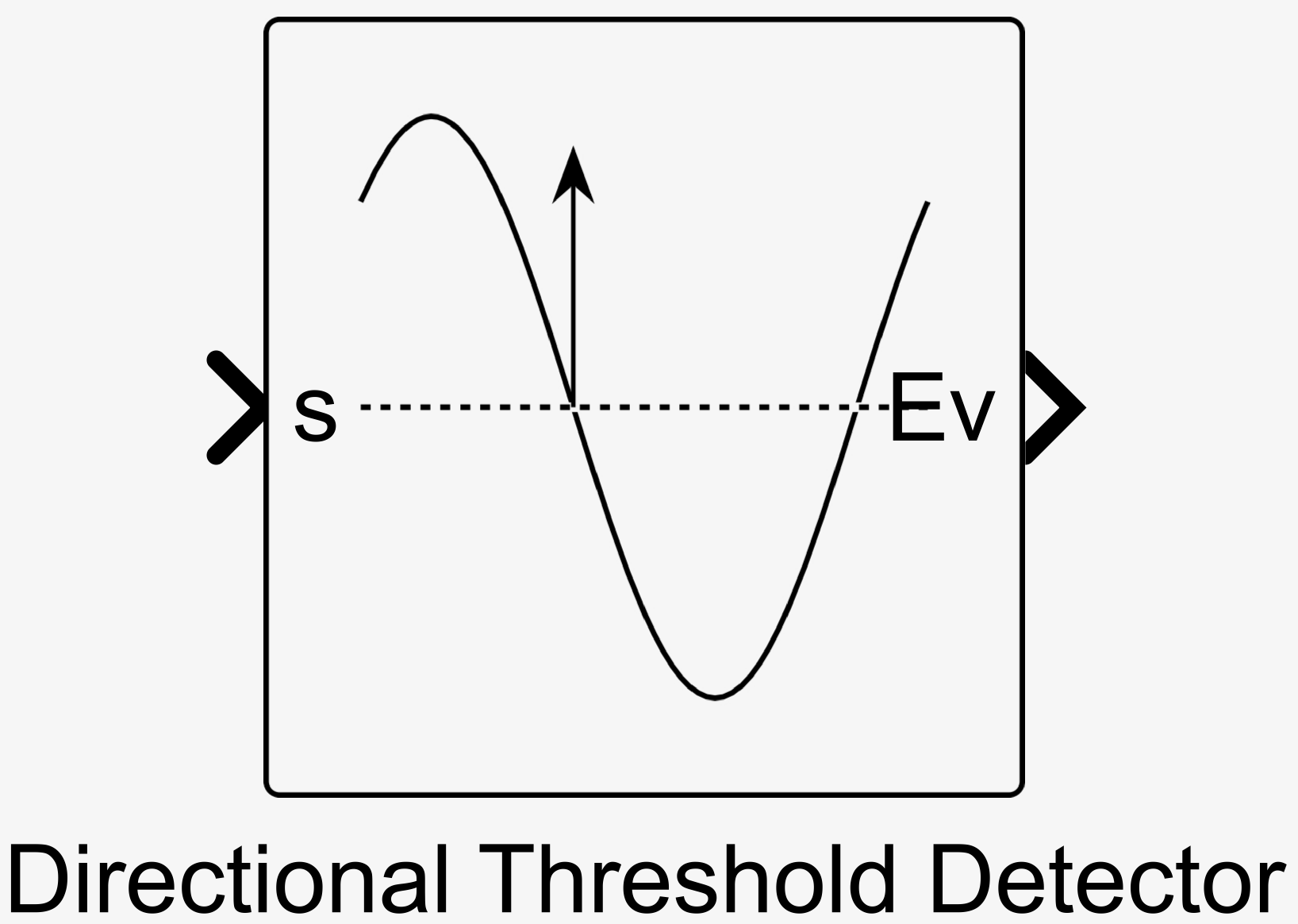
Block generating an event when the input signal crosses a threshold from a certain direction (above to below or below to above). The block is compose of an input block that generates a current to an internal type III
Neuron. The input block can be mathematically described as:\[\begin{split}\begin{aligned} I &= g\sigma(as - d)\\ \end{aligned}\end{split}\]where \(g\) is the gain, \(a\) the slope, and \(d\) the bias of the input and \(I\) is the current sent to the internal type III neuron.
- Input:
s (analog) – Input selection signal \(s\).
- Output:
Ev (boolean) – Output positive events signal. See
Neuronfor details.- Alternative Output:
V (analog) – Output positive voltage signal. Output is computed from volatage \(V_n\) of neuron by \(\text{V} = g_{\text{out}}\sigma(a_{\text{out}}V_n- - d_{\text{out}})\). See
Neuronfor details.- Parameters:
Input Gain – The gain \(g\). Default value is -0.5.
Input Bias – The bias \(d\). Default value is 0.
Input Slope – The slope \(a\). Default value is 10.
Timescale – The timescale \(\tau\) of the internal neuron. Default value is 0.004.
Output Type – The exposed output channel. Can be set to ‘Events’ or ‘Voltage’. Default value is ‘Events’.
Output Conductance – The output conductance \(g_{\text{out}}\) used if voltage output is selected. Default value is 1.
Output Bias – The output bias \(d_{\text{out}}\) used if voltage output is selected. Default value is 0.
Output Slope – The output slope \(a_{\text{out}}\) used if voltage output is selected. Default value is 1.
- Bistable Relay
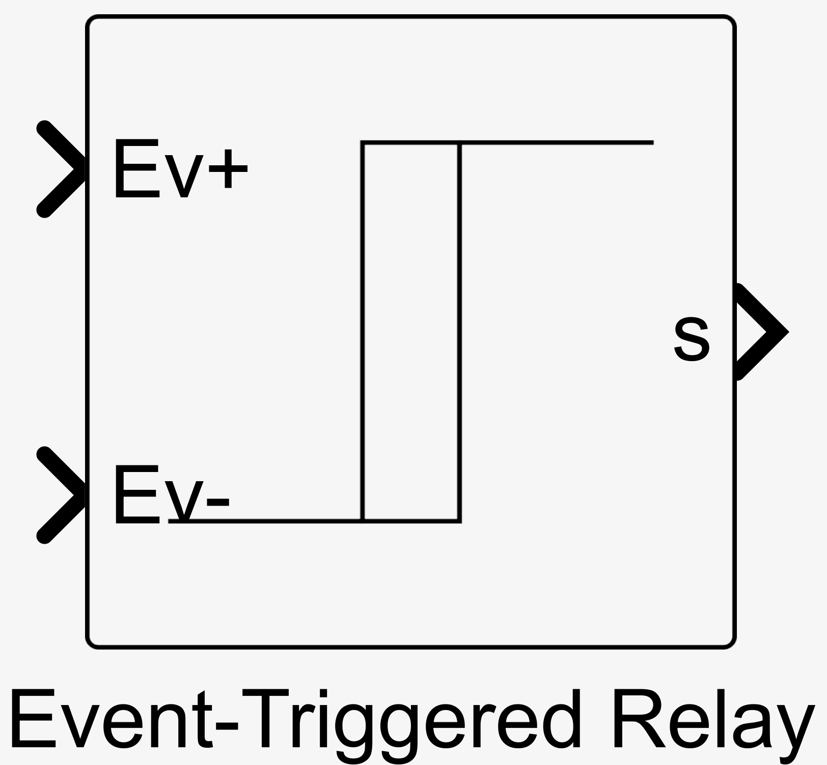
Block capable of storing the polarity of the last event received. The blocks can be mathematically described as:
\[\begin{split}\begin{aligned} \tau\tau_r\dot{v} &= s + g_{+}\text{In}_{+} + g_{-}\text{In}_{-} - v\\ s &= g\sigma(av - d) \end{aligned}\end{split}\]where \(\tau\) is the timescale, \(\tau_r\) the relative timescale, \(g_+\) the positive input gain, \(g_-\) the negative input gain and \(g\) the gain, \(a\) the slope, and \(d\) the bias of the feedback function.
- Inputs:
Ev+ (boolean) – Input positive events signal \(\text{Ev}_+\) such that \(\text{In}_+ = \text{Ev}_+\).
Ev- (boolean) – Input negative events signal \(\text{Ev}_-\) such that \(\text{In}_- = \text{Ev}_-\).
- Alternative Inputs:
V+ (analog) – Input positive voltage signal \(\text{V}_+\) such that \(\text{In}_+ = \sigma(a_{\text{in}+}\text{V}_+ - d_{\text{in}+})\).
V- (analog) – Input negative voltage signal \(\text{V}_-\) such that \(\text{In}_- = \sigma(a_{\text{in}-}\text{V}_- - d_{\text{in}-})\).
- Optional Inputs:
gsyn_p (analog)– The gain \(g_+\) as described in the parameter section.
gsyn_m (analog)– The gain \(g_-\) as described in the parameter section.
- Output:
s (analog) – Input selection signal \(s\).
- Parameters:
Feedback Gain – The gain \(g\) of the feedback function. Default value is 1.
Feedback Biases – The biases \(d\) of the feedback function. Default value is 0.
Feedback Slopes – The slopes \(a\) of the feedback function. Default value is 1.
Positive Input Gain – The positive input gain \(g_+\). Default value is 1.
Negative Input Gain – The negative input gain \(g_-\). Default value is 1.
Timescale – The timescale \(\tau\). Default value is 0.004.
Relative Timescale – The relative timescale \(\tau_r\). Default value is 0.01.
Input-Output Type – The exposed input-output channels. Can be set to ‘Events’ or ‘Voltage’. Default value is ‘Events’.
Input Biases – The input biases \(d_{\text{in}\pm}\) used if voltage input is selected. Default value is 0.
Input Slopes – The input slopes \(a_{\text{in}\pm}\) used if voltage input is selected. Default value is 1.
- Noise on Signal
Block adding band-limited white noise to the input signal. The blocks can be mathematically described as:
\[\begin{aligned} y &= x + W(t) \end{aligned}\]where \(W(t)\) is a band-limited white noise process with zero mean, standard deviation \(\sigma\), and a correlation time \(\tau\tau_r\) with \(\tau\) the timescale and \(\tau_r\) the relative timescale.
- Input:
In (analog) – Input signal \(x\).
- Output:
Out (analog) – Output signal \(y\).
- Parameters:
Noise Power – The square of the standard deviation \(P = \sigma^2\) of the noise. Default value is 1.
Timescale – The timescale \(\tau\). Default value is 0.004.
Relative Timescale – The relative timescale \(\tau_r\). Default value is 1.
Seed – The seed of the random number generator, a value of -1 specifies a random seed. Default value is -1.