Neural Blocks#
- Neuron#
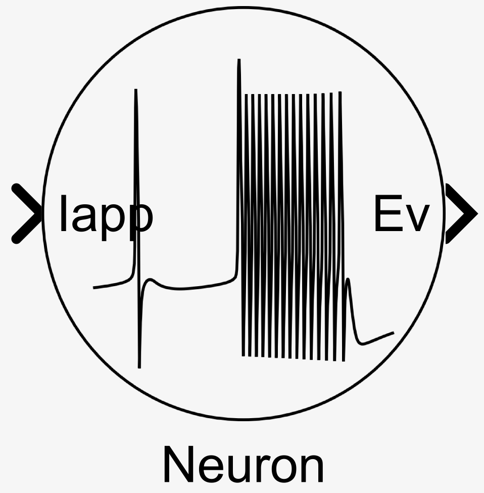
Block implementing a neuron based on the mixed-feedback theory inspired by Ribar and Sepulchre[1]. The block can be mathematically described as:
\[\begin{split}\begin{aligned} \tau\tau_m\dot{V} &= I + V_0 + I_0 + i_{f-} - i_{s+} + i_{s-} - i_{u+} + i_{u-} - V\label{eq:neur_start}\\ i_{f-} &= g_{f-}\left(\tanh\left(a_{f+}v_f-d_{f-}\right) - \tanh\left(a_{f-}V_0-d_{f-}\right)\right)\\ i_{s+} &= g_{s+}\left(\tanh\left(a_{s-}v_s-d_{s+}\right) - \tanh\left(a_{s+}V_0-d_{s+}\right)\right)\\ i_{s-} &= g_{s-}\left(\tanh\left(a_{s+}v_s-d_{s-}\right) - \tanh\left(a_{s-}V_0-d_{s-}\right)\right)\\ i_{u+} &= g_{u+}\left(\tanh\left(a_{u-}v_u-d_{u+}\right) - \tanh\left(a_{u+}V_0-d_{u+}\right)\right)\\ i_{u-} &= g_{u-}\left(\tanh\left(a_{u+}v_u-d_{u-}\right) - \tanh\left(a_{u-}V_0-d_{u-}\right)\right)\\ \tau\tau_f\dot{v_f} &= v - v_f\\ \tau\tau_s\dot{v_s} &= v - v_s\\ \tau\tau_u\dot{v_u} &= v - v_u\\ \delta &= \mathop{H}(V-d_\delta). \end{aligned}\end{split}\]where \(g_*\) are the conductances, \(a_*\) the slopes, \(d_*\) the biases, \(d_\delta\) the event threshold, \(\tau\) the timescale, \(\tau_*\) the relative timescales, \(V_0\) the resting potential, \(I_0\) the bias current, and \(\mathop{H}\) the Heaviside step function. The conductances \(g_*\) can optionnaly be set as an input.
- Input:
Iapp (analog) – Input current \(I\).
- Optional Input:
g__ (analog)– The one or multiple conductances \(g_*\) as described in the parameter section.
- Output(s):
Ev (boolean) – Output events \(\delta\).
V (analog) – Output voltage \(V\)
- Parameters:
Gains – The conductances \(g_*\). Default value is 1 for all.
Gains Source – Where to get the conductances value from. Can be set to ‘Internal’ or ‘External’. Default value is ‘Internal’.
Biases – The biases \(d_*\). Default value is 0 for all.
Slopes – The slopes \(a_*\). Default value is 1 for all.
Timescale – The timescale \(\tau\). Default value is 0.004.
Relative Membrane Timescale – The relative timescale \(\tau_f\). Default value is 0.1.
Relative Fast Timescale – The relative timescale \(\tau_m\). Default value is 0.1.
Relative Slow Timescale – The relative timescale \(\tau_s\). Default value is 4.
Relative Ultra-Slow Timescale – The relative timescale \(\tau_u\). Default value is 200.
Base Applied Current – The base applied current \(I_0\). Default value is 0.
Base Voltage – The base voltage \(V_0\). Default value is 0.
Base Event Threshold – The base event threshold \(d_\delta\). Default value is 0. Value is ignored if Output is set to ‘Voltage’.
Output – The exposed output channel(s). Can be set to ‘Events’, ‘Voltage’ or ‘Both’. Default value is ‘Events’.
- Synapse with Facilitation
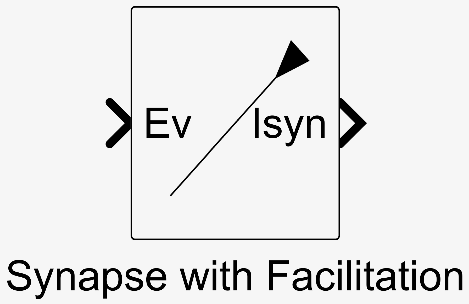
Block implementing a synapse with a facilitation mechanism. The blocks can be mathematically described as:
\[\begin{split}\begin{aligned} \tau\tau_r\dot{v} &= \text{In} - v\\ I &= g\sigma(av - d) \end{aligned}\end{split}\]where \(\tau\) the timescale, \(\tau_r\) the relative timescale, \(g\) is the conductance, \(a\) the slope, and \(d\) the bias. The conductance \(g\) can optionnaly be set as an input.
- Input:
Ev (boolean) – Input events signal \(\text{Ev}\) such that \(\text{In} = \text{Ev}\).
- Alternative Input:
V (analog) – Input voltage \(\text{V}\) such that \(\text{In} = g_\text{in}\sigma(a_\text{in}\text{V} - d_\text{in})\).
- Optional Input:
gsyn (analog)– The conductances \(g\) as described in the parameter section.
- Output:
Isyn (analog) – Output current \(I\).
- Parameters:
Conductance – The conductance \(g\). Default value is 0.
Conductance Source – Where to get the conductance value from. Can be set to ‘Internal’ or ‘External’. Default value is ‘Internal’.
Bias – The bias \(d\). Default value is 0.
Slope – The slope \(a\). Default value is 1.
Timescale – The timescale \(\tau\). Default value is 0.004.
Relative Timescale – The relative timescale \(\tau_r\). Default value is 10.
Input Type – The exposed input channel. Can be set to ‘Events’ or ‘Voltage’. Default value is ‘Events’.
Input Conductance – The input conductance \(g_\text{in}\) used if voltage input is selected. Default value is 1.
Input Bias – The input bias \(d_\text{in}\) used if voltage input is selected. Default value is 0.
Input Slope – The input slope \(a_\text{in}\) used if voltage input is selected. Default value is 1.
- Synapse with Depression
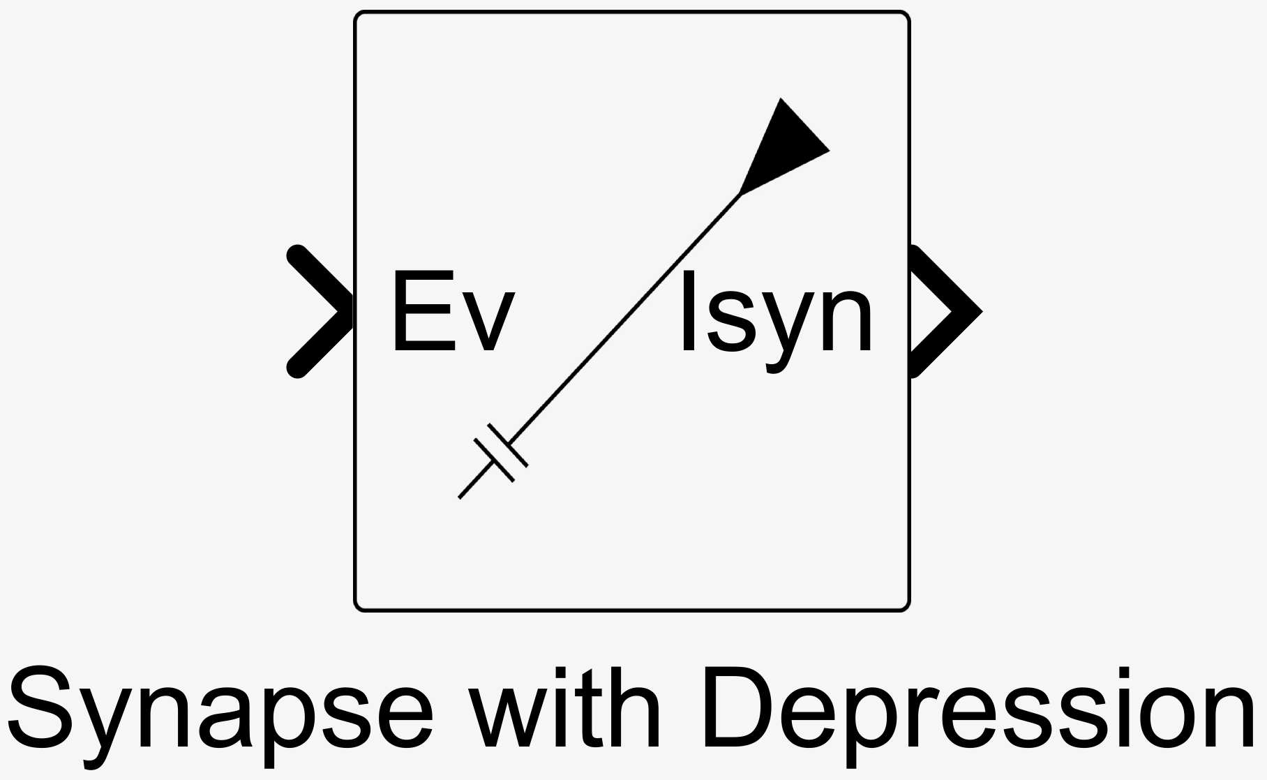
Block implementing a synapse with a depression mechanism on top of a facilitation mechanism. The blocks can be mathematically described as:
\[\begin{split}\begin{aligned} \tau\tau_r\dot{v} &= \text{In} - v\\ \tau\tau_d\dot{v_d} &= \text{In} - v_d\\ g_d(v_d) &= g\sigma(a_dv_d - d_d)\\ I &= g_d(v_d)\sigma(av - d) \end{aligned}\end{split}\]where \(\tau\) the timescale, \(\tau_r\) the relative timescale, \(\tau_d\) the relative depression timescale, \(g\) is the conductance, \(a\) the slope, \(d\) the bias, \(a_d\) the depression slope, and \(d_d\) the depression bias. The conductance \(g\) can optionnaly be set as an input.
- Input:
Ev (boolean) – Input events signal \(\text{Ev}\) such that \(\text{In} = \text{Ev}\).
- Alternative Input:
V (analog) – Input voltage \(\text{V}\) such that \(\text{In} = g_\text{in}\sigma(a_\text{in}\text{V} - d_\text{in})\).
- Optional Input:
gsyn (analog)– The conductances \(g\) as described in the parameter section.
- Output:
Isyn (analog) – Output current \(I\).
- Parameters:
Conductance – The conductance \(g\). Default value is 0.
Conductance Source – Where to get the conductance value from. Can be set to ‘Internal’ or ‘External’. Default value is ‘Internal’.
Bias – The bias \(d\). Default value is 0.
Depression Bias – The depression bias \(d_d\). Default value is 0.
Slope – The slope \(a\). Default value is 1.
Depression Slope – The depression slope \(a_d\). Default value is 1.
Timescale – The timescale \(\tau\). Default value is 0.004.
Relative Timescale – The relative timescale \(\tau_r\). Default value is 0.
Relative Depression Timescale – The relative depression timescale \(\tau_d\). Default value is 100.
Input Type – The exposed input channel. Can be set to ‘Events’ or ‘Voltage’. Default value is ‘Events’.
Input Conductance – The input conductance \(g_\text{in}\) used if voltage input is selected. Default value is 1.
Input Bias – The input bias \(d_\text{in}\) used if voltage input is selected. Default value is 0.
Input Slope – The input slope \(a_\text{in}\) used if voltage input is selected. Default value is 1.
- Modulatory Synapse
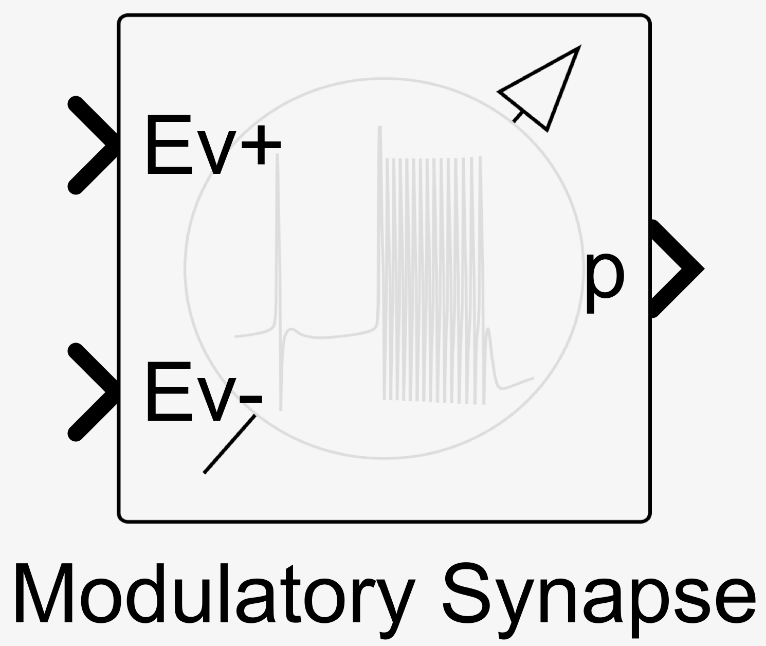
Block implementing a synapse emulating a modulation mechanism. The blocks can be mathematically described as:
\[\begin{aligned} \tau\tau_r\dot{p} &= \bar{p} + g_+\text{In}_+ - g_-\text{In}_- - p \end{aligned}\]where \(\tau\) the timescale, \(\tau_r\) the relative timescale, \(\bar{p}\) the base parameter value, \(g_+\) the positive conductance, and \(g_-\) the negative conductance. The conductance \(g_+\) and \(g_-\) can optionnaly be set as an input.
- Inputs:
Ev+ (boolean) – Input events signal \(\text{Ev+}\) such that \(\text{In}_+ = \text{Ev+}\).
Ev- (boolean) – Input events signal \(\text{Ev-}\) such that \(\text{In}_- = \text{Ev-}\).
- Alternative Inputs:
V+ (analog) – Input positive voltage \(\text{V+}\) such that \(\text{In}_+ = \sigma(a_\text{in+}\text{V+} - d_\text{in+})\).
V- (analog) – Input negative voltage \(\text{V-}\) such that \(\text{In}_- = \sigma(a_\text{in-}\text{V-} - d_\text{in-})\).
- Optional Inputs:
gsyn_p (analog)– The conductances \(g_+\) as described in the parameter section.
gsyn_m (analog)– The conductances \(g_-\) as described in the parameter section.
- Output:
p (analog) – Output parameter \(p\).
- Parameters:
Base Parameter Value – The base parameter value \(\bar{p}\). Default value is 0.
Positive Conductance – The positive conductance \(g_+\). Default value is 0.
Negative Conductance – The negative conductance \(g_-\). Default value is 0.
Positive Conductance Source – Where to get the conductances value from. Can be set to ‘Internal’ or ‘External’. Default value is ‘Internal’.
Negative Conductance Source – Where to get the conductances value from. Can be set to ‘Internal’ or ‘External’. Default value is ‘Internal’.
Timescale – The timescale \(\tau\). Default value is 0.004.
Relative Timescale – The relative timescale \(\tau_r\). Default value is 1000.
Input Type – The exposed input channels. Can be set to ‘Events’ or ‘Voltage’. Default value is ‘Events’.
Input Positive Bias – The input positive bias \(d_\text{in+}\) used if voltage input is selected. Default value is 0.
Input Negative Bias – The input negative bias \(d_\text{in-}\) used if voltage input is selected. Default value is 0.
Input Positive Slope – The input positive slope \(a_\text{in+}\) used if voltage input is selected. Default value is 1.
Input Negative Slope – The input negative slope \(a_\text{in-}\) used if voltage input is selected. Default value is 1.